The term management takes on many forms. In fact the most basic definition “to control or direct” about says it all. When used in aviation we find structured organizations with employees having specific functions or specialties and it is up to the department manager to set the priorities in terms of which aircraft needs which specialist and the percentage of the work force to get the aircraft back on the line for a scheduled trip. Often the chief of maintenance has considerations including available manpower, schedules, and costs that all have to be weighed to set in motion the best possible plan to achieve the desired results.
In many modern aircraft, the cockpit crew are often referred to as “flight deck managers.” Piloting skills, although still important, are being supplemented with proficiency in varying kinds of computer technology.
It was not all that many years ago when methods of navigation were up to the discretion of the pilot. Do they tune an automatic direction finder (ADF) or set a frequency for a very high frequency omni directional range (VOR) station, perhaps look out the flight deck windows and follow familiar geography including highways and railroad tracks?
The point here is that a flight management system (FMS) is primarily a navigation system computer with some mind-boggling capabilities.
Computerized systems as a rule can be broken down into four main areas; the computer itself, inputs or sensors, programming or controls and the work performed otherwise known as outputs.
Functions performed by FMS can vary with both manufacturers and models; once again the primary function of a FMS is to facilitate navigation. In addition to information to the flight crew, data can also be sent via steering channels into the auto flight system. Many systems contain extensive memories that can be programmed with specific aircraft information including performance. This can enable sophisticated computations that can assist the pilots in knowing the range of the aircraft in varying conditions and if fuel starvation could occur prior to reaching the predicted destination.
When the FMS is initialized it first has to be made aware of its present position. In many cases the last known latitude and longitude coordinates are committed to memory at the time of system shutdown and are then recalled during the power up process. In other cases various navigation sensors such as global positioning systems (GPS) will automatically communicate with the FMS to provide position reference. Once initialization has been accomplished then the flight crew can establish a flight plan to the destination. This consists of establishing a set of waypoints accommodating standard instrument departures (SIDs), standard terminal arrival routes (STARs), and designated airways and allowing the system to calculate the best way to get from the point of departure to the destination.
The System
Typical flight management systems consist of a control display unit (CDU), flight management or navigation computer, global position sensor, and a data loader.
The flight management computer accepts information from numerous navigation sensors including VOR, distance measuring equipment (DME), and GPS. Data from each sensor is prioritized based on its known percentage of error and can be blended to provide the most accurate position information.
The computer has a programmable database containing known radio navigation stations along with their tunable frequencies, airports, SIDs, and STARs as well as approach data for runways. Due to frequent changes the database requires updating every 28 days. This is accomplished by loading electronic media files into some type of data loader which can vary from a floppy drive, zip, or even a compact disc. In some cases the data loader can be used to download diagnostic or fault data to the same type of electronic media. This information can then be interrogated to allow more accurate fault analysis. Some aircraft will have a multipurpose unit where in addition to using some form of electronic memory a laptop computer could also be connected allowing flight crews to create flight plans in their offices or at a hotel room and then when they get to the aircraft they can transfer data to the FMS.
Many systems include a custom database as well. Here, information pertaining to aircraft performance, common flight plans, and waypoints can be stored.
FMS computers take on many forms. In some cases they are contained within the control display unit and in other cases they are a stand-alone device and may consist of an integrated circuit card contained within a card cage or can even be a separate box located somewhere within the aircraft. Some such boxes utilize a backup battery to maintain certain memory functions. In this case there should be a scheduled maintenance event where the battery is replaced.
Although different versions of FMS computers may exist, and even though two different types of aircraft utilize a similar type FMS, that is no guarantee that all the components will be interchangeable. When replacement of an FMS computer is required it is imperative to take some actions to transfer the custom database to a second FMS or when possible to the data loader. Then after the replacement device has been successfully installed and tested, reload the custom information.
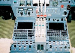
Control display units are used to communicate with the flight management computer as well as other associated devices. It enables display and modification of various parameters as well as allowing the flight crew to select the various FMS operating modes. The display will illustrate the menu functions plus provide messages to the pilot advising of system malfunctions and recommended crew actions. Typically there are additional fault advisory warnings usually located in the direct line of sight of either the pilot or co-pilot which serves as an “attention getter” so the crew will then refer to the CDU message. Many CDUs will not have adequate space in the display area to bring up all stored messages. Using the “NEXT” function key is in many cases the means of viewing messages that would otherwise be concealed.
FMS navigation is based on using all the available navigation sensors to fly from point to point along a planned flight route. Waypoints can be selected based on information contained within the navigation database or simply pilot-selected coordinates. Once this information has been entered, the FMS can generate steering commands or at least visual cues advising the flight crew on how to manipulate the aircraft from one predefined position to the next.
After power is applied to a FMS an initial position has to be determined. This process can be accomplished manually by entering a known position such as a runway threshold, gate, or even an airport. When GPS sensors are available, they can routinely be used to provide initial as well as update position. If GPS is the only source of information, it will typically not provide any aircraft heading reference until the aircraft begins to move.
To navigate, the FMS uses data from all available sensors including GPS, VOR, DME, attitude, and heading as well as air data. For VOR and DME navigation, the FMS again depends on correct position information when it was activated. Based on initial position, the system will scan the navigation database and select navigation stations determined to be the best choices for that area. Once the radio navigation station is tuned, the navigation computer verifies it is receiving the selected ground station by monitoring the transmitted station identifier. Once confirmation is made the nav station data is then blended with the other sensors to achieve the optimum position reference. As the aircraft moves, the process continues with the FMS scanning and tuning the navigation radios to the next navigation aid along the chosen route. In the event the aircraft is passing directly over a radio navigation station the system can recognize it is within the “Cone of Confusion” and will disregard erroneous information until the aircraft has exited the cone.
Global positioning systems may be used as a primary navigation means in oceanic and remote areas. Most navigation systems have to sense at least four satellites to begin the positioning process and can process signals up to 10 or 11 at any given time. The more satellites, the greater the accuracy.
Status and integrity of the GPS position solution is made available to the crew so they can be sure their required navigation accuracy is met throughout the flight. GPS receiver autonomous integrity monitoring otherwise known as RAIM is the term associated with the proper functioning of GPS.
In the event no navigation signal information is available to the FMS it will begin computing the aircraft course using the dead reckoning (DR) mode. A situation such as this will enable the FMS to estimate the location based on the last known position, along with heading and airspeed. Anytime DR is used the system will post a message advising the flight crew.
Other checks and balances are used including comparisons of all sensor data. In the event one input advised the FMS navigation computer that it is sensing a position that is not in agreement with the others, a message will be displayed to the flight crew telling them they need to verify their present position plus be advised that there may be a problem with one of the system inputs.
Maintenance Support
Regulatory guidance when selecting and installing a multi-sensor navigation system can be found in Advisory Circulars issued by the FAA. One example is AC 20-130A, which gives a basic description and lists typical navigation sensors. Often airframe manufacturers will not select specific FMS for their products but will allow their customers to choose devices that provide them with specific functions or at least commonality with the rest of their aircraft fleet. Flight management systems are often installed in aircraft that are already in service by a variety of Supplemental Type Certificates (STC) or in some cases by an FAA Form 337 under a field approval. In a first-time installation where aircraft performance values such as engine thrust and reference speeds are part of the package then an STC has to be created.
In cases where the FMS is not considered standard equipment, the FMS installation manual and supporting documentation will most frequently serve as acceptable data for maintenance support, ensuring continued airworthiness and providing tests that will permit return to service.
Many systems do contain an internal diagnostic system and when problems arise they can be noted and recorded. Most systems will go through a thorough self-check including all sensors during the start-up phase of operation. If, for example, the GPS was not operational at that time a GPS failure would be noted on a system status page.
Many of the reported discrepancies concerning multi-sensor navigation systems have to do with improper setup. A minor error when putting in an initial position can result in a dramatic error several hours into the flight or if the aircraft is moved prior to completion of the initialization process. Another frequent cause of FMS problems deals with voltage drop during operation. Should aircraft electrical system voltage drop below the operating threshold of the FMS, pre-loaded data such as a flight plan could be lost. Many airframe manufacturers will install backup batteries in the flight management system power circuit to ensure momentary lapses will not erase pertinent information.
It has been determined that on average, flight crews will utilize around 25 percent of the overall capabilities of their flight management system. This fact is very important when it comes to clearing discrepancies. Dual FMS is the norm when dealing with most airliners and business aircraft. In the event of a reported navigation error it may be advantageous to find out if the second system also had a problem. When both systems are in error, more often than not the problem is related to initialization. Sounds like a management problem.


